THE SMALL GEOTECHNICAL CENTRIFUGE OF THE UNIVERSITY OF DELFT
1 INTRODUCTION
Centrifuge research is helpful in investigating the behaviour of soil and other granular materials. For example, consider the behaviour of a vertical cut in clay. It is well known that at some depth failure of the cut occurs. It is not possible to investigate the stability of this problem in a small scale model at 1g condition, because the shear stresses are so low with respect to the cohesion that failure will never occur. In a centrifuge, however, the body force can be increased in an artificial way, so that even in a small model the same shear stresses can be realized as in the prototype problem. With this technique it is possible to use small scale models to visualize the behaviour of large size problems. Clay is a typical example of a material with a strong stress dependent behaviour but also materials like sand behave differently under different stress levels. If tests are performed on small samples of wet sand the results are strongly dependent on the capillary pressure because the cohesion caused by this pressure is of the same magnitude as the interparticle stresses. In several practical problems the simulation of the stress dependent behaviour is of importance in order to make reliable predictions.
The late sixties can be considered as the beginning of a new area for centrifuge modelling. Several centrifuges were built for geotechnical work and a large variety of problems were studied by this technique (Kimura et al., 1998). The tendency was to increase the size of the devices, so that the costs of tests became very high. For several geotechnical problems, however, the use of a small centrifuge is quite adequate. By making an optimal choice between size and facilities and using up-to-date electronics and computer control effective tests can also be performed in a small centrifuge.
In 1988 the development of a small geotechnical beam centrifuge with a diameter of two metres was started at the Geotechnical Laboratory of the University of Delft. The device was operational in 1990. Test devices with a dimension of 300x400x450 mm and a weight of 300 N can be accelerated up to 300g. A small geotechnical centrifuge is relatively cheap to operate, and the development of the equipment did not take so long compared to a big centrifuge. To enable the performance of advanced tests in flight, the carriers of the centrifuge were made large enough to contain computer-controlled devices. Because the costs of operation are low, the device is suitable to perform trial and error tests. Modification of the centrifuge for different tests is simple, so that a flexible operation is obtained. The test containers and actuators are, in general, so small that they can be conducted by one person. This is convenient during the preparation of the tests and leads to good reproducibility of the soil samples. This is important if the results of similar tests have to be compared.
A disadvantage of a small centrifuge is the limitation in the use of sensors during a test. This restriction, however, can be compensated partly by using image processing techniques in video images taken with the on-board video camera.
Miniature devices have been developed for performing advanced tests in flight, such as: loading, displacement and controlling the supply of sand, water and compressed air. The devices operate under software control, which runs in a single board PC compatible computer located in the spinning part of the centrifuge. The signals from load cells, pressure transducers and other sensors are received by the on-board computer without interference of slip rings. The computer is assessable in a normal way via slip rings and commercial available line drivers. The test devices are driven by small DC motors, which are manipulated by the on board computer.
Several devices have been developed to prepare sand and clay samples. To improve the reproducibility sample preparation is automated as much as possible. A special centrifuge has been built to consolidate clay slurry, in order to obtain a very soft normally consolidated clay. Several different research projects were conducted in the centrifuge, i.e.: sliding behaviour of spudcan foundations, stability of dikes during wave overtopping, gas blowouts and cratering, stability of embankments during widening, shear band analysis, buckling behaviour large diameter piles, uplift load buried pipe lines, simulation suction pile installation, pile driving and pollution transport. Recently some orientating tests in new area’s are performed, they are: influence surface waves on the sea floor and simulation of earthquakes.
Several project were carried out as a 6 month graduate study. In recent years the centrifuge was in operation almost every day, hence the flexibility is demonstrated by the fact that three quite different model tests were performed on some days.
2 THE SMALL GEOTECHNICAL CENTRIFUGE OF THE UNIVERSITY OF DELFT
2.1 Mechanical part
The geotechnical centrifuge at the University of Delft was designed by the Geotechnical Laboratory of the Department of Civil Engineering and was built by the mechanical workshop of the University.
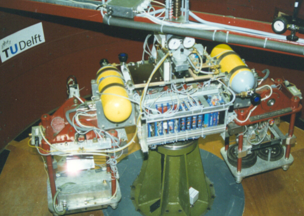
The electronic systems were designed and built by the Geotechnical Laboratory. The advantage of the in-house design is that the system can be expanded and modified under internal supervision, which guarantees a good interaction between the facilities of the device and the tests. The centrifuge frame is fixed to the floor and bears the vertical axis and the protection shield (Fig.1). A beam with a length of 1500 mm is connected to the axis, so that it can be rotated in the horizontal plane. Two swinging carriers are connected to the beam by means of brackets, so that the total effective diameter is 2400mm. The carriers are formed by two plates at a distance of 450 mm apart, which are connected to each other by four cylindrical steel beams. The surface of the plates is 400 x 300 mm . The potential danger from the spinning part of the centrifuge is minimized by a protection shield of steel (thickness = 5 mm) that forms a large cylindrical box. A second shield, 50 cm outside the first, is made of wooden plates. The gap between the two shields is filled with concrete blocks and granular material.
A
B
Fig1 a) Photograph of the small centrifuge of the University of Delft. b) Schematic drawing.
This fill gives additional safety against flying projectiles and the weight stabilizes the device.
The centrifuge is driven by an electric motor of 18 kW via a hydraulic speed control unit. This is enough power to achieve an artificial gravity of 300g. The hydraulic speed controller is manipulated by a step motor, which is interfaced to the speed control computer. A computer program has been developed to adjust the speed of the centrifuge using the signal of a tachometer. Several options are available to control the speed. It is, for example possible to make the acceleration dependent on time or on other test parameters, such as the pore water pressure in a clay sample.
2.2 Measuring facilities
The system electronics enables the performance of computer-controlled tests in flight (Fig.2). To minimize the number of slip rings the control system is placed in the spinning part of the centrifuge. The control unit contains a small single board computer (180x120x25mm ; 486CPU; 66MHz; 16Mbyte RAM; 32Mbyte solid state disk), a 12-bit analog to digital converter with a 16-channel multiplexer, two voltage controlled outputs of 8 Ampere each, two 16-bit counters and several digital input/output channels. For additional data storage a 1Gbyte hard disk unit is placed just in the centre of the centrifuge. The signals from the sensors are conditioned by on-board amplifiers. Eight power slip rings are available to feed the electronics and the actuators. 24 high quality slip rings are used to transmit the more sensitive signals,
Fig.2 Diagram of the electronic control and measuring system.
such as, for example, two video lines and the connection between the on-board computer and the PC in the control room. By means of commercial available line driver units is was possible to realize a normal access to the board computer.
A special feature is that several phenomena can be measured using the video images. In this technique the video images of the in flight test are captured by the frame grabber in the PC and processed until the relevant parameters are isolated. Image processing can be used to visualize and digitize the surface deformation of clay and sand samples or to digitize the consolidation of a clay layer (Allersma,1990). This technique has proven to be very useful in several research projects.
3 THE TEST EQUIPMENT
Several devices have been developed by the Geotechnical Laboratory of the University of Delft to perform tests in flight. The mechanical equipment, electronic system and control software are designed in all details by the laboratory. The following devices are available: to dimensional loading system, in flight sand sprinkler, vane apparatus, gas supply system, water supply system, pile driving unit, suction pile simulator, surface wave simulator, earthquake simulator and pollution supply system.
3.1 Two dimensional loading system
The two dimensional loading system (Fig. 3) can be considered as a universal tool, which can be used for several tests. Two guiding systems based on linear ball bearings and axes of tempered steel guarantee a low friction translation in two perpendicular directions. The system is driven by two miniature DC motors. The translation is achieved by means of a screw spindle with a translation of 1 mm per revolution. The number of revolutions is counted by means of small pulse generators, which also detect the direction of rotation. One revolution is
A
B
Fig.3 a) Photograph of the two dimensional loading device, mounted in the centrifuge. b) Schematic drawing of the loading device.
equivalent to 200 pulses. A special interface has been built to make it possible for the pulses to be used in the control program in order to determine displacements in the two perpendicular directions. The loads in the two perpendicular directions are measured by means of load cells. The outputs of the load cells are multiplied and can be used in a computer program via the multiplexer and the analog-to-digital-converter. Sufficient information is available to perform load or displacement controlled tests. Furthermore the device can be used as a simple robot to manipulate a test during flight. Loads of more than 5 kN can be applied by the system. The accuracy of the measurement of the displacement (determined at 100g by image processing) is better that 0.1 mm, where the maximum displacement is about 50 mm. Up to now the device has been used at gravitation levels of more than 150 g. The weight of the two dimensional loading device is approximately 10 kg. It takes about ten minutes to install the loading system in the centrifuge. As an example, the typical output of a test with a spudcan foundation on sand is shown in Fig.4. In this test series the sliding resistance of the foundation element at different vertical loads is investigated, in order to make predictions about
Fig.4 Typical output of a sliding test of a spudcan on sand
the behaviour of offshore platforms during heavy storms (Allersma et al., 1997). Spudcans with a diameter of more than 14 metres can be simulated. Thanks to the small size of the models it is very easy to examine the influence of modifications of the design, such as skirts, surface roughness, pins, hinge etc (Allersma, 1997). Other tests that can be performed are, for example: anchors, horizontal bearing capacity suction piles, uplift load buried pipes, bulldozer, footing, excavation.
3.2 In flight sand sprinkler
A computer controlled sand sprinkler has been developed to make embankments in flight. The device consists of a hopper, which can be translated easily by means of linear ball bearings and axes of tempered steel (Fig. 5a). The weight of the device is approximately 10 kg. The translation ( range is 150 mm) is realized by means of a small DC motor. The position of the hopper is detected by means of a pulse wheel and a 16 bit counter, which can be accessed in the program of the control computer. The sprinkler system is designed in such a way that no close seals are required. An axis is located in the outlet of the hopper in such a way that the granular material flows only when the axis is rotated. This mechanism has proven to be reliable up to 120g. The axis of the sprinkler system is also driven by a small DC motor and the amount of deposited sand is detected by counting the number of revolutions by means of a pulse wheel. Several options can be assessed in the control program. It is possible to sprinkle sand layer by layer or at one particular location. Optionally, the control program of the sand sprinkler also reads the output of pressure transducers, which can be placed in the clay layer. The creation of a dike during sand supply and the deformation of the clay can be monitored by a video camera. The deformation of the clay is made visible by means of a grid. Software has been developed by the laboratory (Allersma, 1990) to digitize the coordinates of the nodes of the grid automatically by means of image processing. The sand
A
B
Fig.5 a) Diagram of the sand sprinkler system. b) Deformation under an embankment on clay.
sprinkler system is used to investigate the stability of dikes and different methods of widening of embankments, which are founded on soft soils (Allersma et al., 1994). It appeared that widening of an embankment causes mainly vertical displacements (Fig.5b) and it could be visualized that the deformation could be influenced by the method of widening (layer by layer or the so called gap method.
3.3 Gas supply system
In some tests gas supply to a soil sample is required. Since the small centrifuge is not equipped with fluid slip rings the gas has to be stored in the spinning section of the centrifuge. To make the storage as compact as possible, two high pressure (200 bar) cylinders of 5 litres each are mounted on the beam of the centrifuge (Fig.1). Before a test is started the cylinders are filled with air by means of a high pressure compressor. A computer controlled air supply system has been developed in order to regulate the gas flow from a distance. The system is shown schematically in Fig.6. The pressure of the supplied air is controlled by a conventional pressure regulator, which is modified in such a way that it can be driven by a small DC motor. The output pressure of the regulator is detected by a pressure transducer and used in the computer program to control the DC motor. A modified valve, which is also driven by a small
Fig.6 Diagram of the air supply system.
Fig.7 Simulation of cratering during a gas blowout in a sand layer with a height of 20m.
DC motor is used to start or stop the gas flow quickly. The gas flow per unit of time is measured by measuring the pressure drop of the gas cylinders during the test. A computer program has been developed to interactively control the gas supply. During a test the cylinder pressure, the test pressure and the gas flow are plotted on the screen. Flow rates of 10 l/s can be reached.
The gas in the high pressure cylinders represents a lot of power, which can be used, in principle, for tests in which large loads or energy are needed. The gas supply system is used to simulate blowouts and cratering (Fig.7) in a sand layer with an equivalent thickness of approximately 20 - 30 metres (Allersma et al., 1994).
3.4 Water supply system
In several geotechnical problems it is required to control water flow in the spinning centrifuge. It is not so easy to control the water supply because rather high pressures (and energy) are required to overcome the acceleration. At this moment two systems are available. In the most simple system the water is circulated by means of an air jet (Fig.8a). The air supply system is used to control the jet. The advantage of this system is that the water supply can be controlled smoothly from zero to maximum flow. The flow rate can be measured by means of a small turbine. A maximum flow of about 10 l/min can be obtained. The water flow rate is measured by means of a small turbine. The water circulation system is used to investigate the stability of dikes during water infiltration, which can occur by wave overtopping (Allersma et al., 1994).
A
B
Fig.8 a) Diagram of the air jet pump. b) Failure of a sand slope, covered with clay, due to water infiltration at the crest.
In Fig.8b it is visualized how a sand slope, which was covered with a thin clay layer, collapses. The most dark area shows sand which is saturated with water. Thanks to the artificial gravity (80g) it was possible to generate a clear freatic surface. The flow direction of the water could be visualized by means of grains of potassium permanganate. An interesting observation was that no shear band mechanism as proposed by e.g. Bishop could be observed. It was found that the clay layer was lifted up by the water pressure. Since friction between clay and sand decreases the own weight of the clay layer causes a crack in the clay. Further damage is caused by gradual erosion of the dike due to seepage. A similar failure mechanism has been observed in a field test.
3.5 Pile driving unit
A simple pile driving unit has been developed to install piles during flight. A diagram of the device is shown in Fig.9a. A cylinder contains a piston, which is lifted up by supplying air shots. After the air has been escaped the piston is falling down. Sufficient impact is obtained to drive piles into sand samples. Since the device would not be very stable if the air is supplied by a flexible tube, a telescope is used to connect the pile driving unit with the air circuit. The telescope stabilizes the driving unit and allows vertical displacement of the device with a minimum of change in the mechanical properties.
A
B
Fig.9 a) Diagram pile driving unit. b) Example of tested piles.
Up to now the pile driving unit is mainly used to examine the buckling behaviour of large diameter piles during driving in sand. Pile driving was required in order to prevent plugging of the soil. It was found that buckling (Fig9b) occurs only if the tip of the pile was damaged slightly.
The pile driving unit can operate in combination with the loading system, so that it is possible to perform a test load after driving, without stopping the centrifuge.
3.6 Suction pile simulator
Suction piles are used offshore as foundation elements or as anchors. Suction piles are attractive thanks to the convenient method of installation. A pile with a diameter of 9m and a height of 10m can be installed in 1 hour, by using a pump only. Although in general installation is not a problem, questions arises when new applications have to be considered. Examples are the installation in layered soils and e.g. onshore applications. Mathematical analysis of this phenomenon is quite delicate, because the soil parameters are changing during installation. The large dimensions make real scale testing not very attractive. Therefore centrifuge tests seems to be the best way to examine this foundation technique. However, a problem arises how to simulate a small pump, and to model a realistic water depth. Both problems can be solved by
Fig.10 Diagram test setup to simulate suction pile installation.
Fig.11 Data measured during a test with a suction pile.
performing the test in a container which can be pressurized. The test setup is shown in Fig. 10. A suction pile is placed on a sand bed. The inside of the suction can is connected via a measuring cylinder with the atmospheric pressure, where a water flow is generated by pressurizing the container. Pressure differences which belong to a water depth of more than 50 metres can be simulated. A typical digitized test result is shown in Fig.11. It was found that there was a linear relation between the required pressure and parameters such as: height, diameter and wall thickness (Allersma et al., 1997).
A separate research project has been carried out to examine the horizontal bearing capacity of large diameter piles. To assure an optimal reproducibility the hollow cylinder piles were placed into the sand box during raining. The two dimensional loading system has been used the perform the test loads. Variables which are tested are attachment height, loading angle and thickness soil layer above the pile. At a loading angle of 20 deg. the optimal attachment point was at 2/5 from the bottom. An interesting result was that the horizontal bearing capacity in sand is optimal if 1/3 of the top of the pile is removed. For this type of research the small size of the models is very convenient, because several effects can be examined in a short period.
3.7 Behaviour of cyclic loaded buried pipes
Sub-sea pipelines used to transport products from production platforms are often trenched and back filled with
A
B
Fig.12 a) Connection between loading system and buried pipe; b) Example of a load-displacement diagram.
soil, in order to protect them from external damage. It sometimes happen that buried pipes are reaching the soil surface again. A possible mechanism is that the pipes are subjected to a cyclic uplift loaded due to buckling, which finds its origin in the fact that the temperature of the transported product is not constant in time. A temperature range of more than 100 deg. Celcius is possible, so that a considerable axial repeating loading and unloading can be expected. In the centrifuge it is examined if the cyclic loading/unloading process influences the uplift resistance of a pipe segment. A rigid pipe segment was buried in sand. The sand was poured carefully in the test box in order to reproduce each sand sample with a variation in density of 0.2%. In the centre the pipe segment was attached to a vertical shaft, which was connected to the loading system (Fig.12a). In the first instance the uplift resistance was determined. In the next tests the pipe segment was subjected to cyclic loading, where the maximum load was 20% below the maximum load. After 20 cycles the maximum load is increased, which process is continued automatically until failure occurs. A typical test result is shown in Fig.12b. It was found that the cyclic loading did not have a significant influence on the ultimate uplift resistance.
In a recent test program the centrifuge was used to investigate the uplift behaviour of buried pipes, where the results are directly used for an offshore design purpose.
A
B
Fig.13 a) Diagram of a simple earthquake simulator. b) Deformation of clay dike after two bumps.
In this case soil from the site was used. Since the models are small only 10 litres of soil was sufficient to perform the tests. Thanks to this small amount the expensive offshore samples could be used twice; namely first for determining soil parameters and next for performing uplift capacity tests. The tests have proven to be very helpful in determining the depth of trench of the buried pipe lines.
3.8 Simulation of earthquakes
In general it is believed that large centrifuges are required to simulate the behaviour of geotechnical structures during earthquakes. Simulation of earthquakes in a geotechnical centrifuge needs high frequencies, because the frequency is proportionally related to the g-level if a pore fluid is used which is 100 times more viscous than water. Models with a weight of 1000N have to be subjected to 20 cycles (displacement ca. 2mm) with a frequency of 100Hz (e.g. 2Hz prototype, at 50 g). In particular when an accurate defined cyclic motion is required a powerful shaking machine is needed. This is in general a heavy machine which can operate only in a big centrifuge.
However, in many cases it is already interesting if mechanisms can be studied. In this case it is not always required that a very well defined wave is generated. In order to examine in how far a small centrifuge can be used for mechanism study a simple earthquake device has been built. A diagram of the device is shown in Fig.13a. A sample box with a weight of approximately 80N can be moved friction free in the horizontal direction. An electro-pneumatic actuator was used to allow a
Fig.14 Example of pollution transport test in partly saturated sand. The contours obtained by image processing.
computer controllable action of the sample box. A single earthquake cycle is simulated by stopping the motion abruptly against a ridged wall. As a demonstration test the behaviour of a clay dike which was founded on sand was investigated. The test was performed at 100g. After reaching the required g level, some time was taken to stabilize the embankment. Next the model was subjected to two bumps. The deformation of the embankment was visualized by subtracting the video images of two test stages (Fig.13b). As can be seen a considerable deformation has taken place. In this test there were no acceleration transducers, so that it is not possible to compare the results with the prototype situation. In principle, however, the on board computer is fast enough to measure the acceleration.
3.9 Simulation of pollution infiltration in soil
LNAPL transport in partly saturated soil can be simulated in a centrifuge (Esposito et al., 1999). The advantage is that the process proceeds faster in the case of viscous fluids and it is possible to generate a groundwater table in a sand sample with a low height. An example of an infiltration test in sand, performed at 30g, is shown in Fig.14. The progress of the infiltration can be digitized by digital image procesing.. The influence of the capillary zone and the groundwater table is good visible. The test results can be used to validate calculation methods.
4 CONCLUSIONS
The small geotechnical centrifuge at the University of Delft has provided successful operation. The small size of the samples means that the machine is very flexible in operation and that tests can be performed in a short time after an idea has been formulated. Due to the application of state-of-the-art electronics, measuring techniques and special tools, advanced tests can be performed in flight. Since the control computer is located in the spinning part of the centrifuge, only a few slip rings are required to interface the spinning equipment with the PC in the control room. The disadvantage of a small centrifuge -limited space for sensors- is overcome by using image processing techniques. A video camera is used to monitor the sample, getting displacements from the video image. Several different types of tests can be performed in the small centrifuge, under which several problems related to offshore engineering. Recently it has been shown that simple earthquake tests can be performed. Thanks to the handy operation and model preparation the centrifuge has proven to be very suitable for educational use. In a short time (one week ) students can design a test, they build equipment and perform a mini test program.
Much attention has been paid to techniques to prepare reproducible samples. Reproducible sand samples can be prepared with an automated sand sprinkler device. In flight consolidation of the slurry is the only way to produce normally consolidated (soft) clay layer. A special centrifuge, built to consolidate clay samples, has increased the capacity of the main centrifuge.
REFERENCES
Allersma H.G.B., 1990. On line measurement of soil deformation in centrifuge tests by image processing. Proc. Int. Conf. on Experimental Mechanics, Copenhagen, 1739-1748.
Allersma, H.G.B., 1997. Centrifuge tests on the influence of shape on the sliding behaviour of spudcans. 8th Int. Conf. on the Behaviour of Off-Shore Structures, Delft, Netherlands, 225-233.
Allersma, H.G.B., B. Hospers, J.G. den Braber, 1997. Centrifuge tests on the sliding behaviour of spudcans. Canadian Geotechnical Journal 34, 658-663.
Allersma, H.G.B., A.P. Kooijman. W. van Niekerk, 1994. Simulation of cratering in a small geotechnical centrifuge. Int. Conf. Centrifuge94, Singapore 31 August-2 Sept. 325-330.
Allersma, H.G.B., I.A.G. Ligtenberg, B.A.N. Koehorst, 1994. Simulation of failure of dikes by water infiltration by waves. Int. Conf. Centrifuge94, Singapore 31 August-2 Sept. 289-294.
Allersma, H.G.B., F.J.A. Plenevaux, J.-F.P.C. Wintgens 1977. Simulation of suction pile installation in sand in a geocentrifuge. 7th Offshore and Polar Eng. Conference, May Hawaii, 761-766.
Allersma, H.G.B., L. Ravenswaay, E. Vos, 1994. Investigation of road widening on soft soils using a small geotechnical., Transp. Res. Record No.1462, Nat. Acad. Press Washinghton, D.C. 47-53.
Esposito, G., H.G.B. Allersma, A.P.S. Salvadurai, 1999. Centrifuge modelling of LNAPL transport in partially saturated sand. J. of Geotechnical and Geoenvironmental Eng.,Vol. 125 no:12, 1066-1071.
Kimura, T., O. Kusakabe, J. Takemura, 1998. Centrifuge98, Proceedings of the International Conference Centrifuge98, Tokyo, Japan, Balkema, Rotterdam.